Importing parts from a JSON file
Cortecloud imports lists of parts, with drilling and machining, from a JSON file in the format described on this page. It is how furniture design software brings the carpenter's project into Cortecloud: your system generates the file and the carpenter loads it into a service.
This integration does not go through the Public API: no credentials or routes are involved. The contract is the file format.
How the carpenter imports the file
The import is done in the carpenter's Cortecloud, in the computer's browser. The mobile app does not have this option.
-
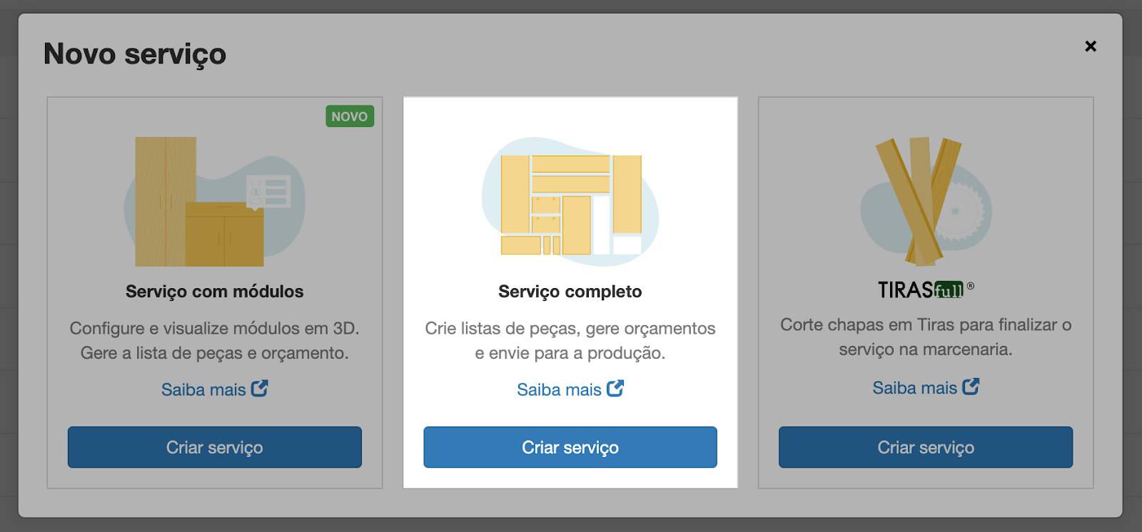
The carpenter creates a new service of type Serviço completo (complete service). Services with modules do not accept part imports.
-
With the service's production line selected (without it the button is disabled), they open Importar peças (import parts) and choose Carregar arquivo Cortecloud (load Cortecloud file), which accepts
.jsonfiles.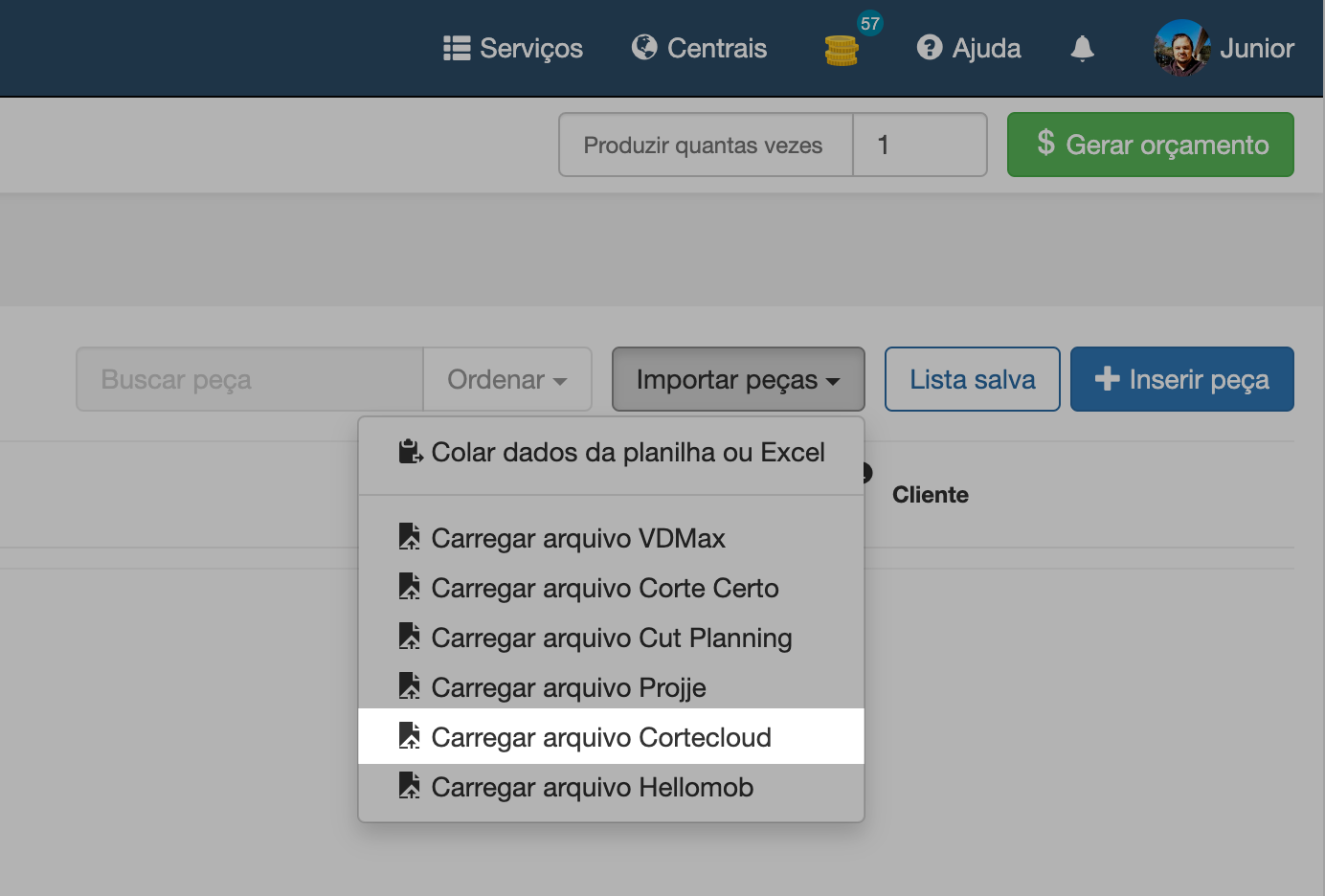
-
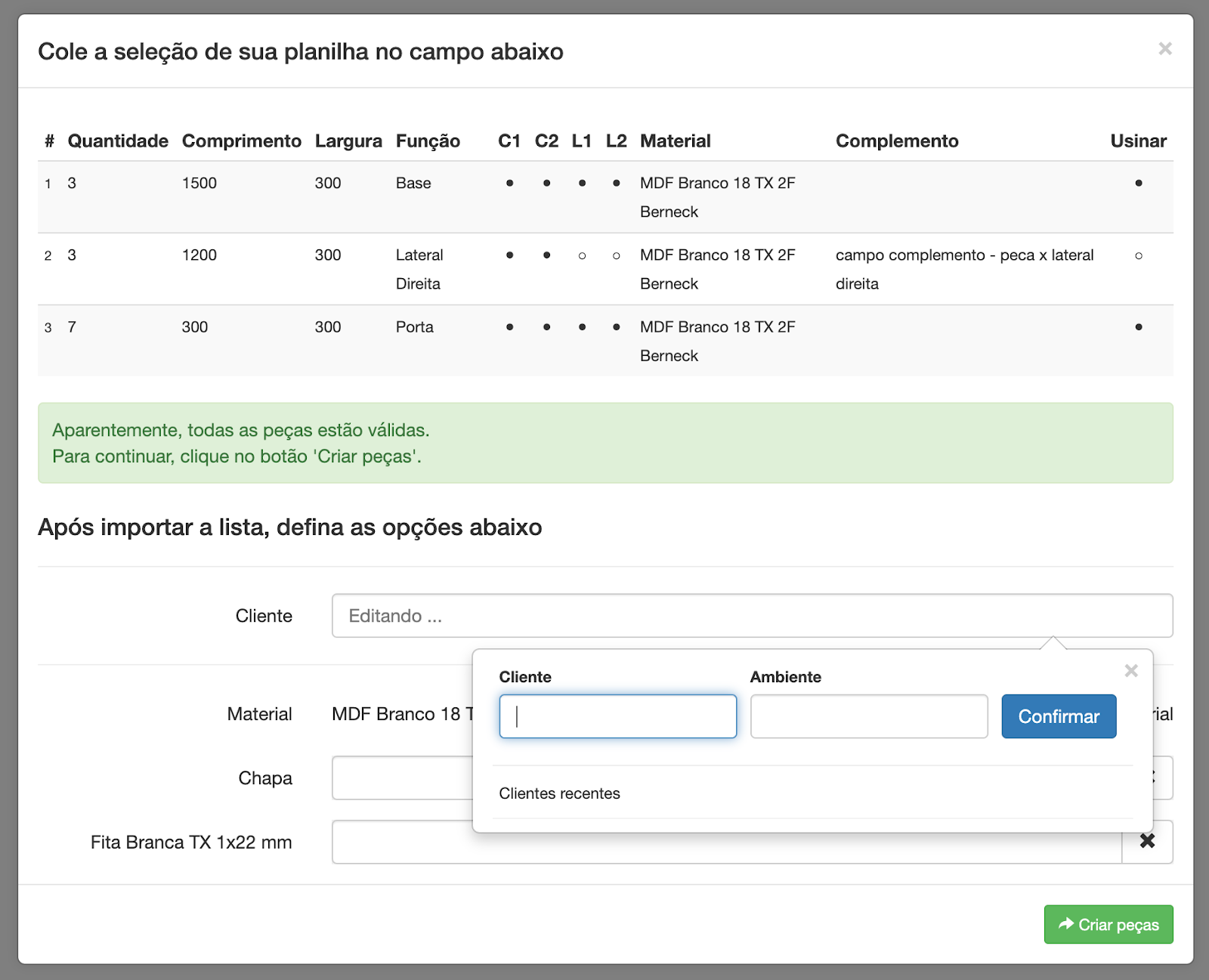
Cortecloud lists the parts in the file and asks them to link each material in the file to a board and an edge banding registered at the service center (see material linking).
-
After the parts are created, the carpenter checks the result in the parts list. For parts with machining, the part thumbnail shows the drilling, with the dimensions of each hole.
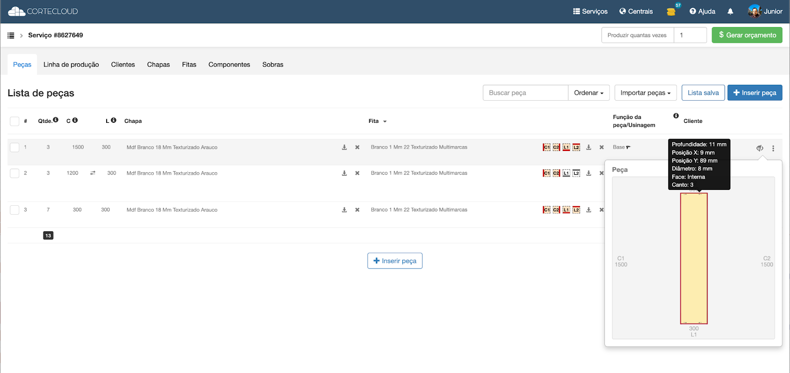
Use this flow to test the file your system generates: with a carpenter account on Cortecloud, load the file into a service and check in each part's thumbnail that the machining ended up where it should.
File structure
The file is an object with the parts list, one entry per part:
{
  "parts": [
    {
      "quantity": 1,
      "c": 500,
      "l": 500,
      "function": "Lateral",
      "complement": "Balcao A",
      "c1": "Branco 0.4",
      "c2": null,
      "l1": null,
      "l2": null,
      "material": "Branco 18",
      "machining": {
        "x": 500,
        "y": 500,
        "z": 18,
        "startSide": 0,
        "horizontalDrills": [
          { "corner": 2, "direction": "XP", "x": 0, "y": 69, "z": 10.5, "depth": 24, "diameter": 8, "face": "i" },
          { "corner": 1, "direction": "XP", "x": 0, "y": 37, "z": 10.5, "depth": 24, "diameter": 8, "face": "i" },
          { "corner": 1, "direction": "XP", "x": 0, "y": 57, "z": 9, "depth": 22, "diameter": 8, "face": "i" },
          { "corner": 2, "direction": "XP", "x": 0, "y": 89, "z": 9, "depth": 22, "diameter": 8, "face": "i" },
          { "corner": 3, "direction": "XP", "x": 0, "y": 69, "z": 10.5, "depth": 24, "diameter": 8, "face": "i" },
          { "corner": 0, "direction": "XP", "x": 0, "y": 37, "z": 10.5, "depth": 24, "diameter": 8, "face": "i" },
          { "corner": 0, "direction": "XP", "x": 0, "y": 57, "z": 9, "depth": 22, "diameter": 8, "face": "i" },
          { "corner": 3, "direction": "XP", "x": 0, "y": 89, "z": 9, "depth": 22, "diameter": 8, "face": "i" }
        ],
        "verticalDrills": [
          { "corner": 2, "bolthole": false, "x": 25, "y": 69, "depth": 12, "diameter": 15, "face": "i" },
          { "corner": 1, "bolthole": false, "x": 25, "y": 37, "depth": 12, "diameter": 15, "face": "i" },
          { "corner": 3, "bolthole": false, "x": 25, "y": 69, "depth": 12, "diameter": 15, "face": "i" },
          { "corner": 0, "bolthole": false, "x": 25, "y": 37, "depth": 12, "diameter": 15, "face": "i" }
        ],
        "furrowMachining": {
          "face": "i",
          "depth": 8,
          "width": 6.7,
          "distance": 15
        },
        "furrowMachiningPair": null
      }
    }
  ]
}
Sample files, with the test cases and the expected result for each one, are in the Serrabits folder on Google Drive.
All measurements are in millimeters.
Part fields
| Field | Type | Description |
|---|---|---|
quantity | integer | Number of identical parts. Must be greater than zero. |
c | number | Length of the part. Must be greater than zero. |
l | number | Width of the part. Must be greater than zero. |
function | text | Function of the part in the furniture (for example, "Side", "Door", "Base"). |
complement | text | Free text that accompanies the part, such as the name of the module or room. |
c1, c2, l1, l2 | text or null | Name of the edge banding applied to each side of the part (see coordinate system), or null for a side without edge banding. |
material | text | Name of the board the part is cut from. |
machining | object or null | Drilling and machining of the part (see machining), or null for a part without machining. |
Parts with quantity, c or l missing, zero or negative are not created.
Material linking
material and the edge bandings (c1, c2, l1, l2) are the names your system uses, not Cortecloud codes. During the import, Cortecloud groups the parts by material and the carpenter chooses, for each material, the service center's board and edge banding that correspond to it. The carpenter can also mark a material to be ignored; its parts are not created.
If no part in the file has material, the carpenter chooses a single board and a single edge banding for all parts.
Each part can use at most two different edge bandings, and the second one is only linked if the service center accepts two edge bandings per part. When the service center does not, the sides with the second edge banding are left without edge banding.
Coordinate system
Machining positions are measured from one of the part's corners, with the part seen from its inner face:
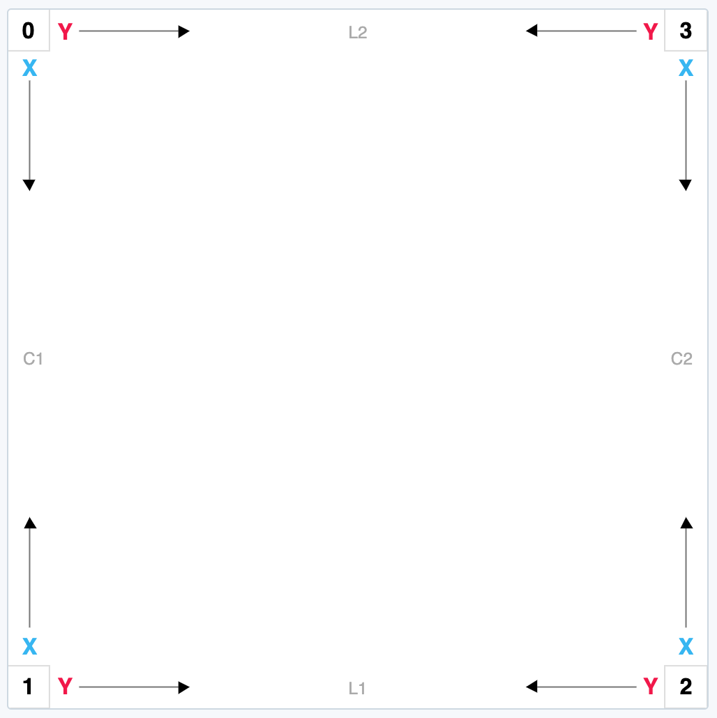
- Corners (
corner):0(top left),1(bottom left),2(bottom right) and3(top right). - Axes: from each corner, X runs along the length (C sides) and Y along the width (L sides), always toward the inside of the part.
- Sides: C1 and C2 are the length sides; L1 and L2, the width sides.
- Segments: each side is also identified by the corners that bound it. C1 is segment 0-1, L1 is 1-2, C2 is 2-3 and L2 is 3-0.
The inner face ("i") is the front face of the part, the one shown in the image; the outer face ("e") is the back.
Machining
The machining object describes the drilling and grooves of a part.
| Field | Description |
|---|---|
x, y, z | Dimensions of the part in the machining coordinate system. With startSide equal to 0, x is the length (c), y is the width (l) and z is the board thickness. |
startSide | 0 keeps the machining as described; 1 rotates the part's entire machining by 90°. |
horizontalDrills | List of horizontal holes: holes drilled into the part's edge, parallel to the faces. |
verticalDrills | List of vertical holes: holes drilled into one of the faces, perpendicular to it. |
furrowMachining | Groove or rabbet on the inner face, or null if there is none. |
furrowMachiningPair | Groove or rabbet on the outer face, or null if there is none. |
Horizontal holes
| Field | Description |
|---|---|
corner | Reference corner for x and y (0 to 3). |
direction | XP for holes on edges L1 or L2 (segments 1-2 and 3-0), which enter the part along the X axis; YP for holes on edges C1 or C2 (segments 0-1 and 2-3), which enter along the Y axis. |
x | Position on the X axis. Must be 0 when direction is XP, because the hole starts at the edge. |
y | Position on the Y axis. Must be 0 when direction is YP. |
z | Position of the hole within the part's thickness, between 0 and the thickness. It is the thickness minus the distance from the center of the hole to the inner face. |
depth | Depth of the hole. |
diameter | Diameter of the hole. |
face | Always "i". |
Examples of z:
- hole in the middle of the thickness of a 15 mm part:
z= 7.5; - hole 7.5 mm from the inner face of a 25 mm part:
z= 25 − 7.5 = 17.5.
Vertical holes
| Field | Description |
|---|---|
corner | Reference corner for x and y (0 to 3). |
x | Position of the center of the hole on the X axis. |
y | Position of the center of the hole on the Y axis. |
depth | Depth of the hole. For a through hole, the board thickness. |
diameter | Diameter of the hole. |
bolthole | true if the hole is a through hole (goes all the way through the part), like assembly holes for bolts; false otherwise. |
face | Face where the hole is drilled: "i" (inner) or "e" (outer). |
Grooves and rabbets
A groove is a channel milled into the face of the part, at some distance from the edge; a rabbet is the same cut placed against the edge. Both are used, for example, to fit the back panel of a piece of furniture. They are always made along side C2 (segment 2-3), over the full length of the part.
furrowMachining and furrowMachiningPair have the same structure:
| Field | Description |
|---|---|
face | "i" in furrowMachining and "e" in furrowMachiningPair. |
depth | Depth of the cut. |
width | Width of the cut. |
distance | Distance from the cut to edge C2. With 0, the cut is a rabbet; with a value greater than zero, a groove. |
furrowMachiningPair is for parts with a groove or rabbet on both faces, such as dividers and shelves that receive a back panel on both sides. The part thumbnail in Cortecloud shows only furrowMachining; the one on the outer face does not appear in it.
When the production line does not machine
Machining is only applied if the service's production line has a machining machine. If it does not, the parts are created without machining: Cortecloud stores the content of machining from the file, but does not apply it to the parts or charge for it in the quote.
Questions
Technical questions about the file format: suporte@serrabits.com.br.